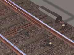
An electric motor driving a point switch and lock.
Model based on a point motor in use at Hornsby, NSW in the 1940s. Details of the motor housing are missing because available images show the housings in the mid-distance only.
Designed for use in conjunction with (a) 'Protrack NSWGR' series as updated with release of <kuid2:368725:49000:2> 'Protrack NSWGR Mesh Library', and (b) an invisible mojunction asset such as <kuid2:44090:1007:1> Invisible Lever.
Place the lock drive between the tracks at a junction with the locking mechanism centred over the sleeper under the leading stretch bar. The crank should then appear secured to the second sleeper in advance of the sleeper with the locking mechanism.
Use rod spline <kuid:368725:30071> 'point rodding, no guide, 1x, NSWGR' to extend from the side port of the point motor to the inner stretch bar. The point motor is on the right side of the track when looking towards the diverging paths of the junction.
Note that this asset cannot by itself switch the direction of a junction. An invisible switch lever must be added to the junction. An association between the invisible lever and the point motor is established through a naming convention. If the invisible lever is named 'HR_16', then the point motor must be named the same way with the suffix '_m' appended: 'HR_16_m'.
The lock animation does not play automatically. The asset's script allows the animation to be operated by a message (major 'operate', minor 'toggle') received from switch-operating assets such as xxxxxxxxxxxxxxxxxxxxxxxxxxxxxxxxxxxxxxxxxxxxxxxxxx.
The lever frame operates a motorised point by sending a message to the point motor, which then sets up the animation sequence: 1) unlock, 2) change junction direction, 3) lock.
The default position of the animation has the lock in the locked position.
 Тип: buildable